6. Debian Application
6.1 Display
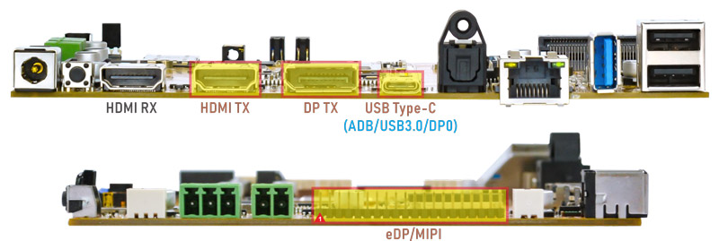
Idea3588 supports Triple-display (DP, HDMI and eDP LCD).
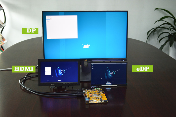
Debian Triple-display
Note
① DP TX and DP0 interface share the VOP resources and cannot be used simultaneously.
② DP0 does not support logo display.
6.2 USB Type-C
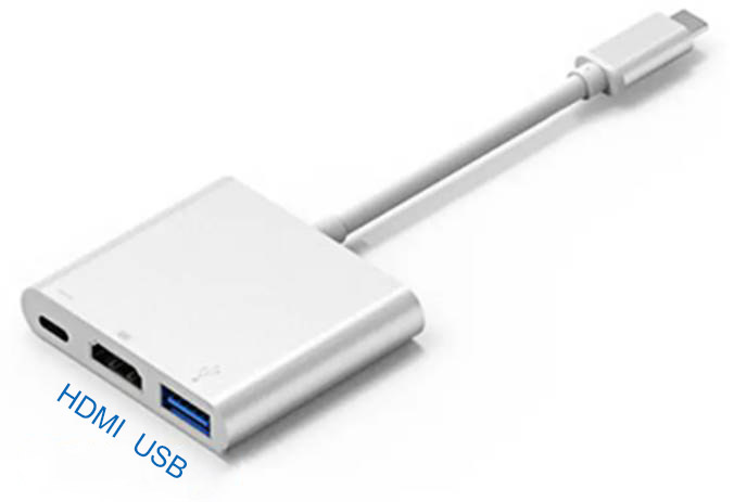
Docking station
Features Supported by the Type-C Interface:
Reversible Design: Allows insertion in either orientation for user convenience.
Data Transmission Roles: Supports flexible designation of host and device roles.
Multiple Protocol Support: Compatible with USB 3.0 and DisplayPort, enabling high-speed data transmission.
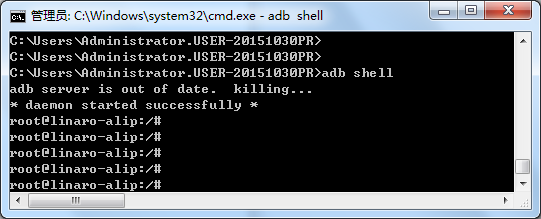
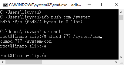
6.2.1 ADB
ADB is the command-line debugging tool for debian, and it can use for system logs, uploading and downloading the files, installing the applications, etc.
❶ Connect the board and PC host with Type-C cable.
❷ Install ADB driver on Windows system.
❸ Press Windows + R to open the Run program. Type cmd and press Enter
❹ Execute command to enable ADB.
adb shell
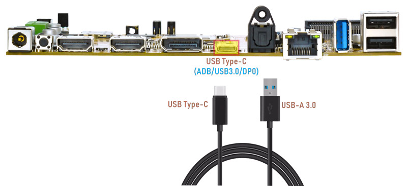
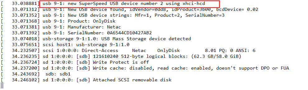
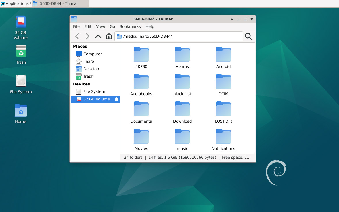
6.2.2 Type-C to USB3.0
Idea3588 supports Type-C to USB3.0. The device can use directly without install any driver.
After inserting the USB3.0 flash drive, an icon will appear on the desktop. Click the icon to automatically mount the device.
6.2.3 DP Alt Mode
DisplayPort Alternate Mode (DP Alt Mode) is a technology that facilitates the transmission of DisplayPort video signals through a USB Type-C interface. It enables devices to output video and audio via a USB-C connection without requiring a dedicated DisplayPort connector. This allows users to connect a display using a single USB-C port while transmitting video, audio, and additional data.
Boardcon has conducted the testing at Type-C to HDMI/DP (3840x2160 @ 60Hz).
Type-C to HDMI
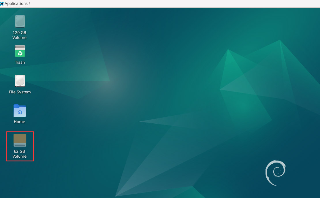
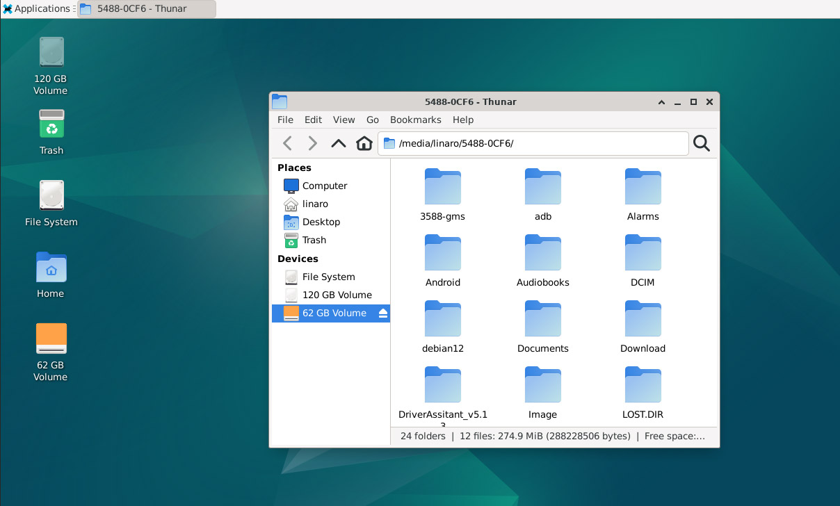
6.3 SD Card
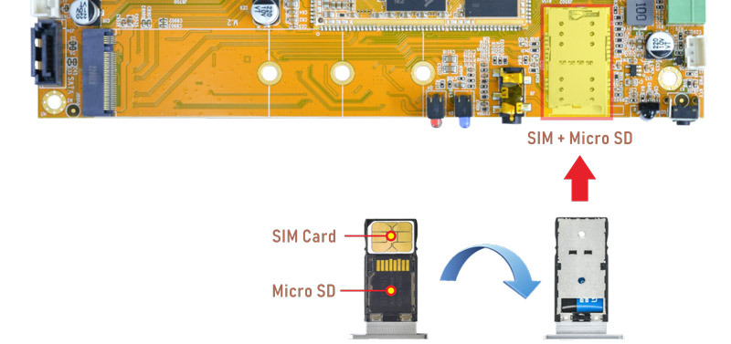
After inserting the SD Card, an icon will appear on the desktop. Click the icon to automatically mount the device.
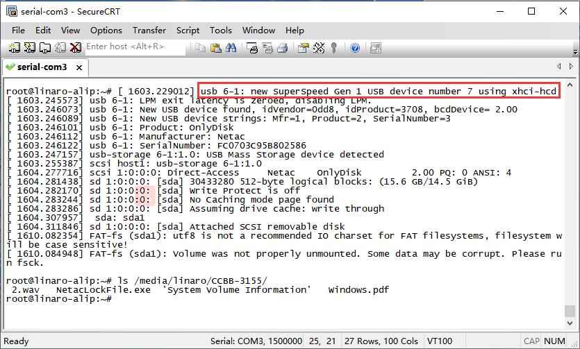
6.4 USB Host
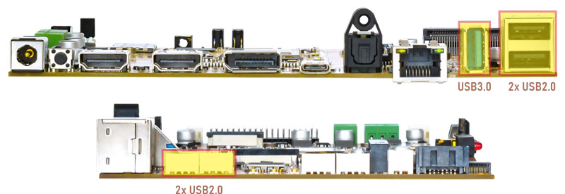
The USB Host can be used to connect USB mouse, USB keyboard, U-Disk or other USB devices.
After inserting the USB flash drive, an icon will appear on the desktop. Click the icon to automatically mount the device.
The USB3.0 default support Superspeed.
6.5 Audio I/O
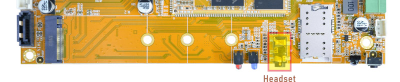
❶ Plug the headphone into the Audio jack
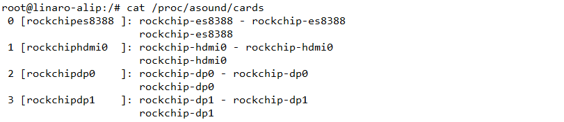
❷ View sound card
cat /proc/asound/cards
❸ Record
arecord -Dhw:0,0 -f cd record.wav //-Dhw:0,0 is card0 and device0
❹ Playback
aplay -Dhw:0,0 record.wav //Adudio output via headset
Audio output description:
aplay -Dhw:0,0 record.wav   //Audio output via Headset
aplay -Dhw:1,0 record.wav   //Audio output via HDMI
aplay -Dhw:2,0 record.wav   //Audio output via Type-C display
aplay -Dhw:3,0 record.wav   //Audio output via DP TX
6.6 Video Playback
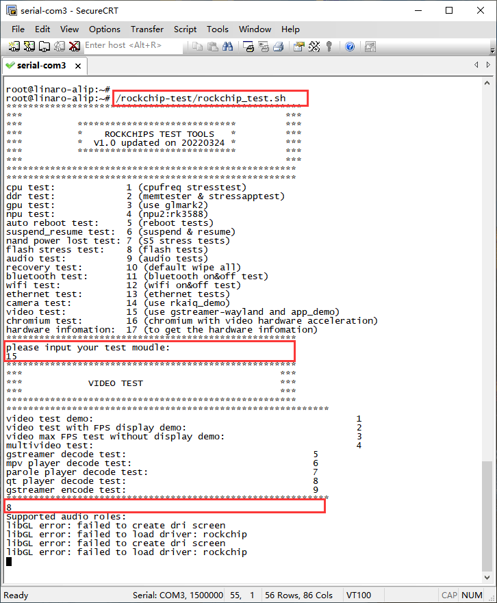
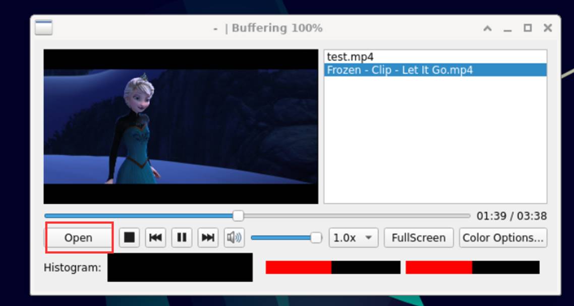
6.6.1 Built-in playback
The script instruction directory is in /rockchip-test/video/, just run it.
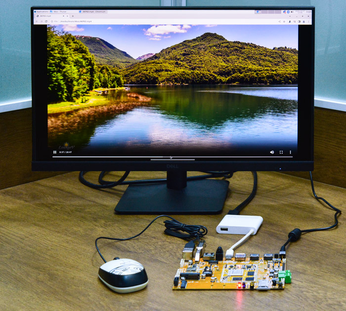
6.6.2 Browser playback
Select Video file, Right-click and select Chromium Browser to play.
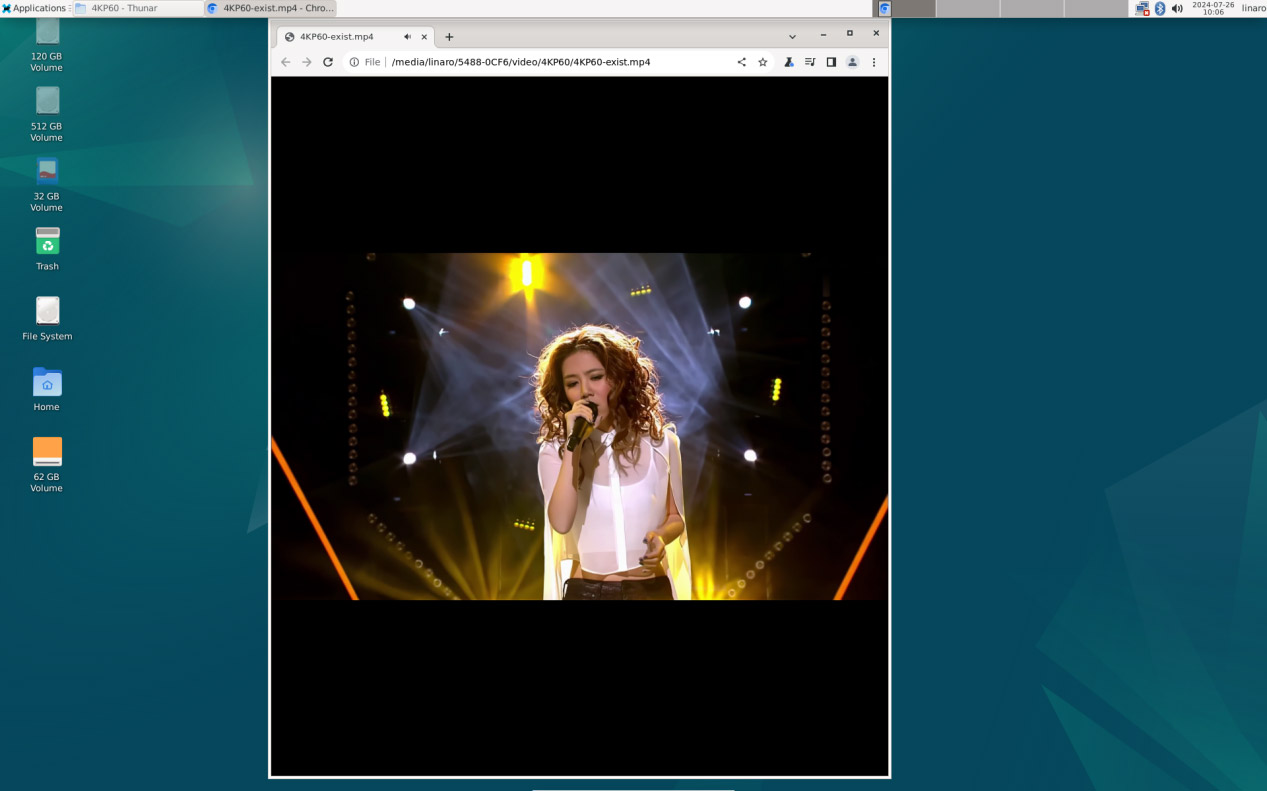
Play video in Chromium Browser
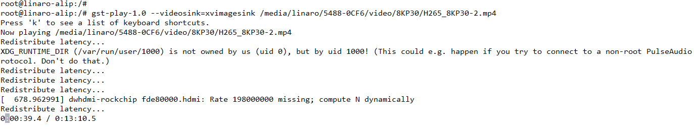
6.6.3 Command line
gst-play-1.0 --videosink=xvimagesink /media/linaro/5488-0CF6/video/8KP30/H265_8KP30-2.mp4
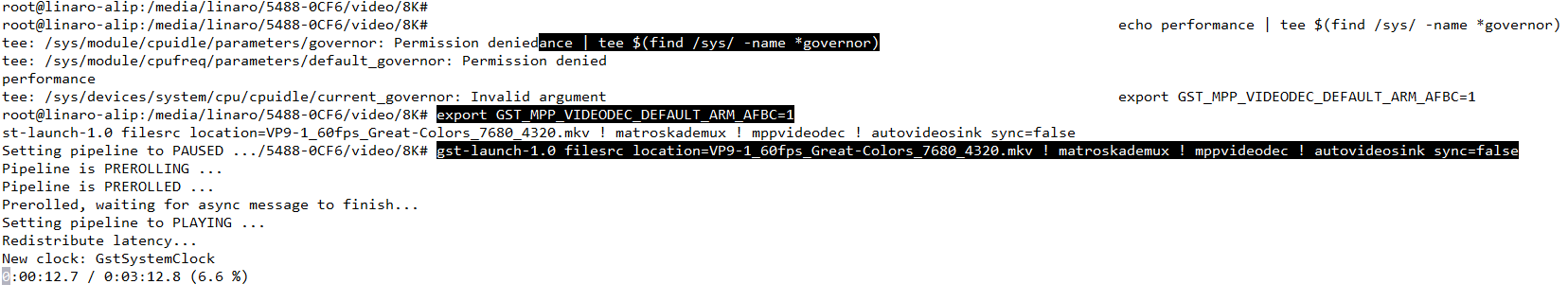
For 8KP60 video playback (No audio output during 8KP60 decoding)
echo performance | tee $(find /sys/ -name *governor)
export GST_MPP_VIDEODEC_DEFAULT_ARM_AFBC=1
gst-launch-1.0 filesrc location=VP9-1_60fps_Great-Colors_7680_4320.mkv ! matroskademux ! mppvideodec ! autovideosink sync=false
6.7 Ethernet
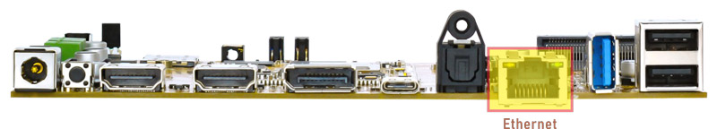
Connect the Board and router with an Ethernet cable.
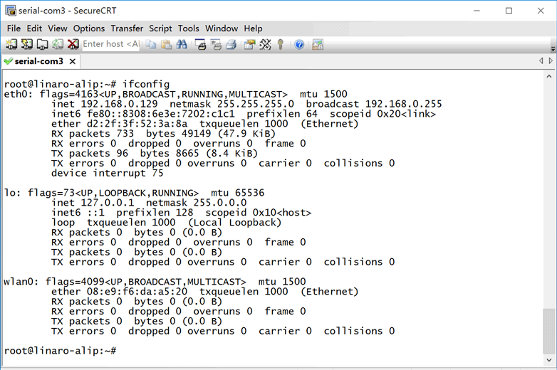
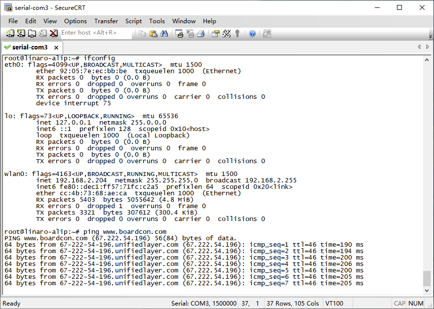
ifconfig //view the status of the network interfaces
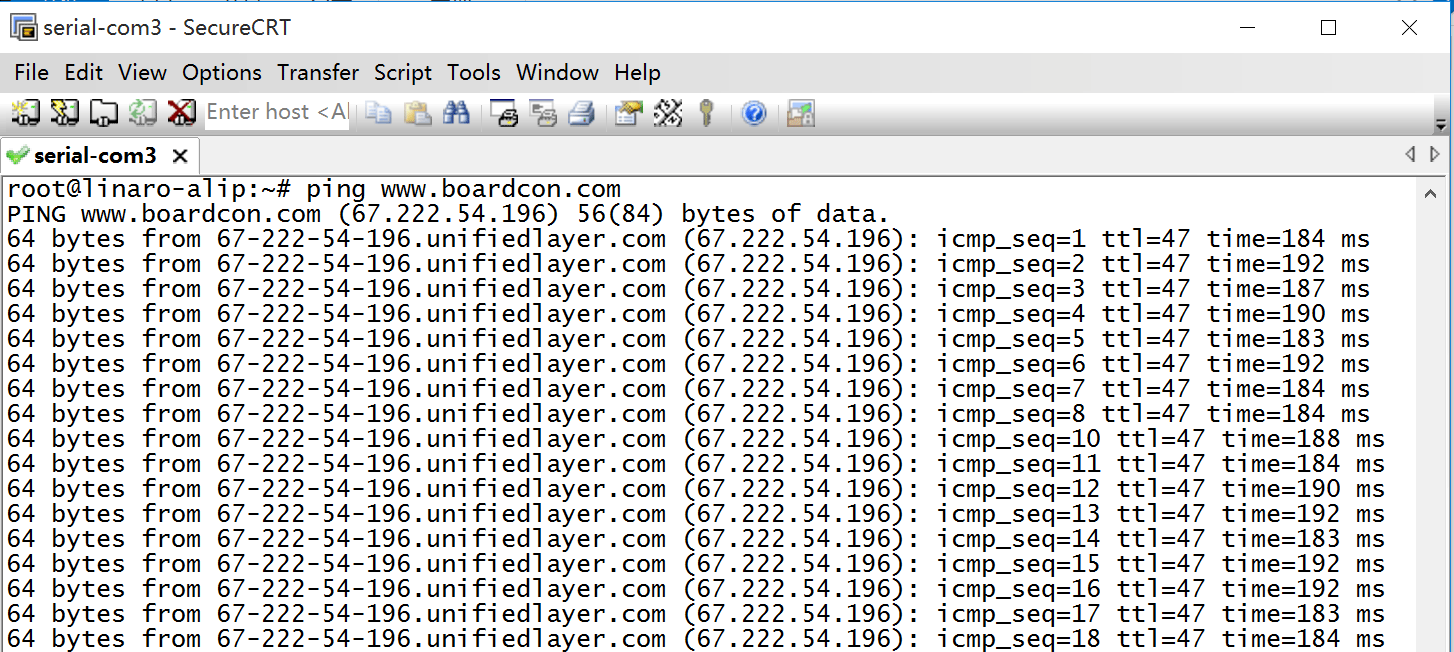
ping -I end1 www.armdesigner.com
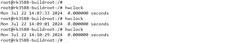
6.8 RTC
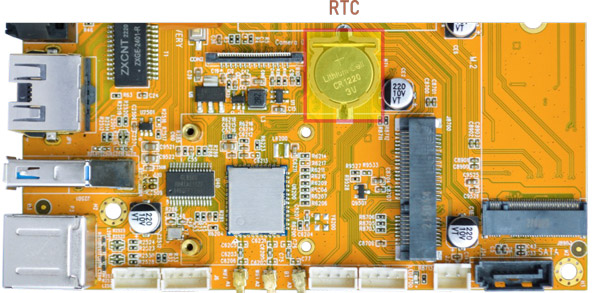
❶ Insert a CR1220 battery before test. It keeps the time running when the main power is off.
❷ Execute command to set system date.
date -s "2024-07-22 12:01:30"     //set system date
hwclock -w                        //set the hardware clock to current system time
hwclock
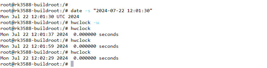
❸ Power off. Wait for a moment, power on again, and then execute the command hwclock. You will find that the time is saved.
6.9 WiFi & Bluetooth
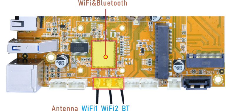
6.9.1 WiFi
❶ Connect the WiFi antenna.
❷ Click the network icon in the top right corner of the UI interface.
❸ Select the SSID from the list of available networks and enter the password.
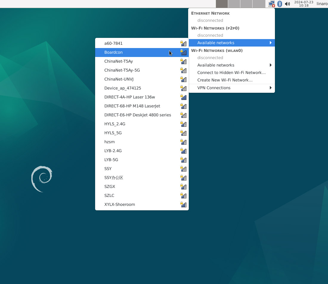
After connected, user can ping URL/IP at terminal to test network.
ifconfig
ping -I wlan0 www.armdesigner.com
6.9.2 Bluetooth
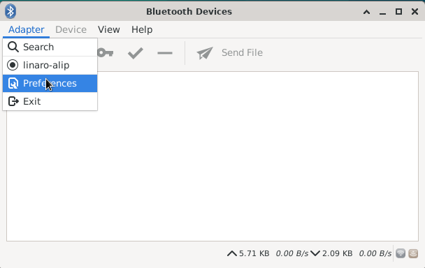
❶ Click the Bluetooth icon in the top right corner of the UI interface, select Devices.. enter the Bluetooth Devices.
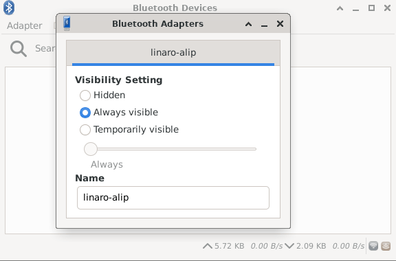
❷ The Bluetooth device name is hidden by default. Set the Bluetooth device name to be visible.
Click Adapter -> Preferences -> Always visible
❸ Click Search to start searching and select the available device in the list to pair.
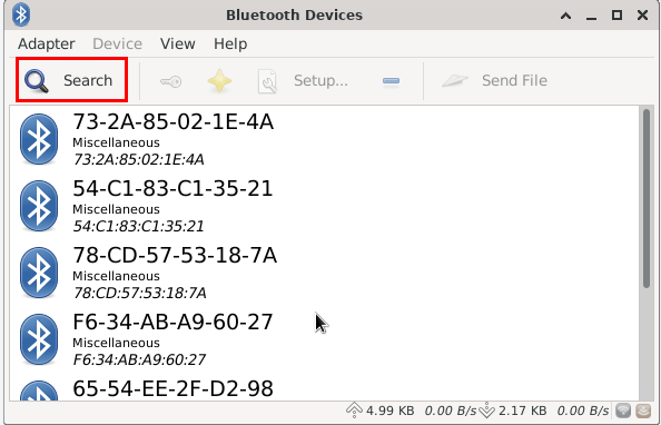
After pairing, devices can connect with each other automatically.
6.10 Camera
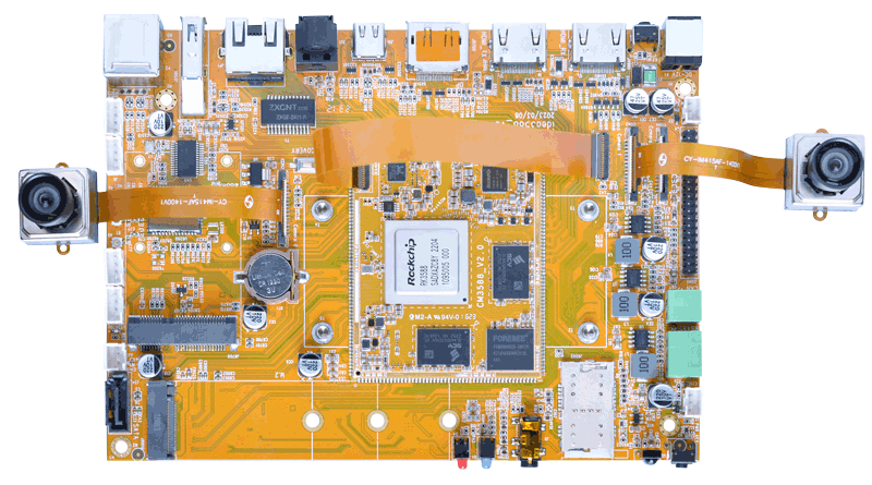
❶ Connect camera0 + camera1.
The Idea3588 Debian system is configured with camera0 + camera1 by default. If you want to preview the cameras normally, please ensure that the camera0 and camera1 are connected.
Since camera0 and camera2 share the signal I2C2, if you want to use camera1 + camera2, please flash a new image.
❷ Check if there are threads in rkisp_3A_server, which indicates automatic startup.
pidof rkaiq_3A_server
The following indicates that rkisp_3A_server has started.

If there are no threads, execute the following command to start rkisp_3A_server
sh /etc/init.d/rkaiq_3A.sh start
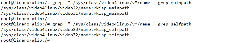
❸ View the device channel
grep "" /sys/class/video4linux/v*/name | grep mainpath
grep "" /sys/class/video4linux/v*/name | grep selfpath
❹ Preview/ record video/ take photos
gst-launch-1.0 v4l2src device=/dev/video22 ! video/x-raw,format=NV12,width=1920,height=1080, framerate=30/1 ! xvimagesink      //preview
gst-launch-1.0 v4l2src device=/dev/video31 ! video/x-raw,format=NV12,width=1920,height=1080, framerate=30/1 ! xvimagesink
gst-launch-1.0 v4l2src device=/dev/video22 num-buffers=100 ! video/x-raw,format=NV12,width=1920,height=1088,framerate=30/1 ! videoconvert ! mpph264enc ! h264parse ! mp4mux !     //record video
gst-launch-1.0 -v v4l2src device=/dev/video22 num-buffers=10 ! video/x-raw,format=NV12,width=1280,height=800 ! mppjpegenc ! multifilesink location=/tmp/test%05d.jpg              //take photos
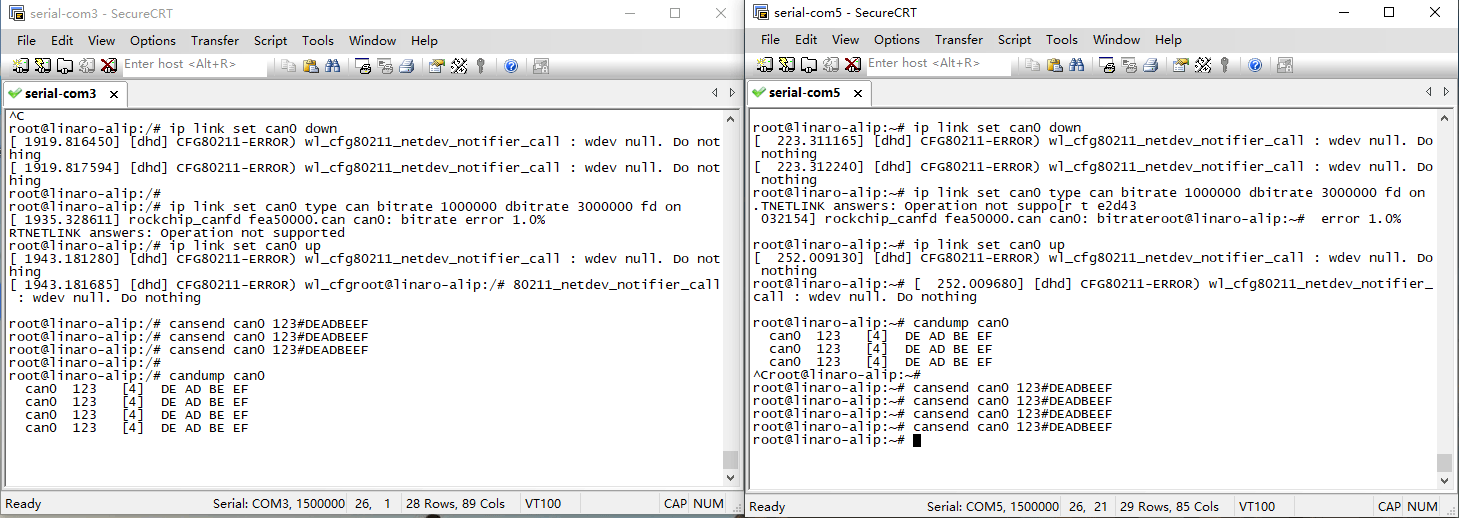
6.11 CAN
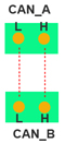
❶ Connect CAN port of Board A and Board B with the test line.
❷ Execute commands at Serial terminal A to set CAN_A as Receiver.
ip link set can0 down
ip link set can0 type can bitrate 1000000 dbitrate 3000000 fd on
ip link set can0 up
candump can0                  //set CAN0 as receiver
❸ Execute commands at Serial terminal B to set CAN_B as Transmitter.
ip link set can0 down
ip link set can0 type can bitrate 1000000 dbitrate 3000000 fd on
ip link set can0 up
cansend can0 123#DEADBEEF      //CAN0 send characters 0xDE 0xAD 0xBE 0xEF
Board A receives the data sent by Board B.
The Transmitter and receiver can be converted by execute the command.
candump can0 //Receiver
or
cansend can0 123#DEADBEEF //Transmitter
6.12 RS485
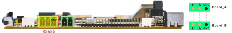
❶ Connect the RS485 port of Board A and B with the test line.
❷ Execute command on the terminal serial ports of board A and board B respectively.
com /dev/ttyS7 115200 8 0 1
❸ Input characters to test RS485 communication.
6.13 UART
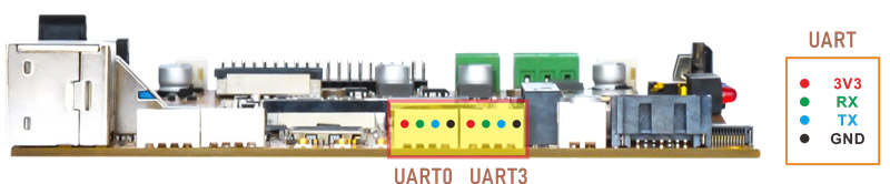
❶ Connect RX and TX of UART.
❷ Execute the command and input characters to test.
com /dev/ttyS0 115200 8 0 1 //test UART0
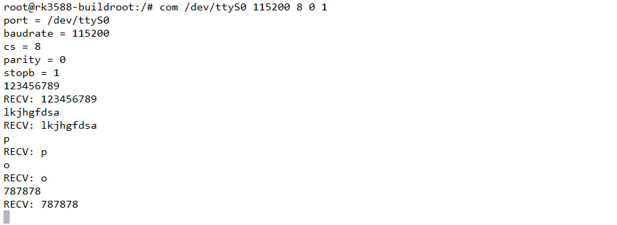
com /dev/ttyS3 115200 8 0 1 //test UART3
6.14 SATA
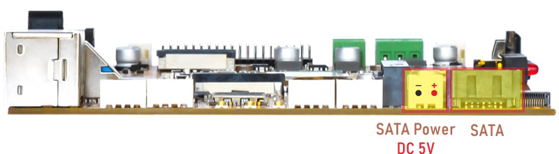
❶ Connect SATA and SATA power to the board and power on.
❷ Format SATA to ext4 format. Idea3588 Debain system only supports ext4 format SATA. If it is in ext4 format, skip this step.
mke2fs -t ext4 /dev/sda //format SATA to ext4
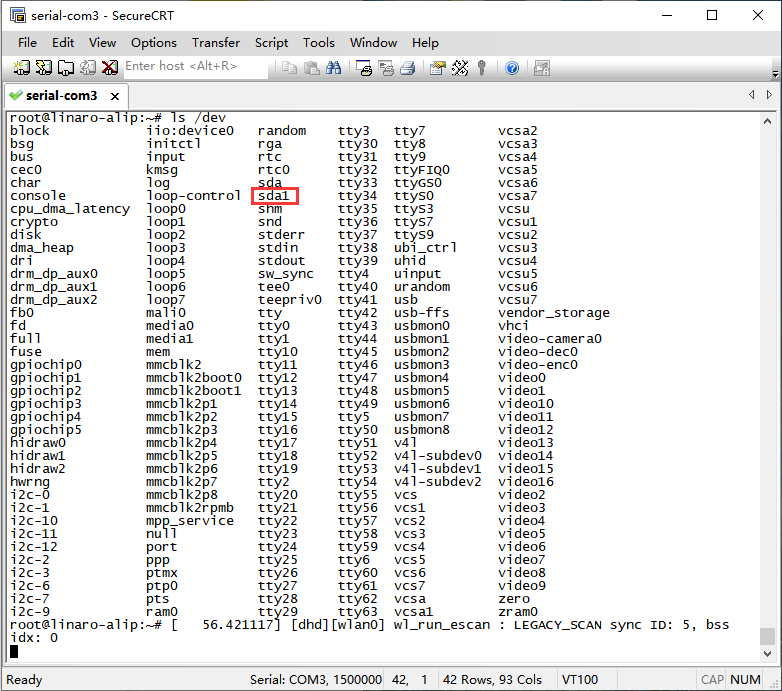
❸ Mount SATA.
ls /dev //view SATA device name
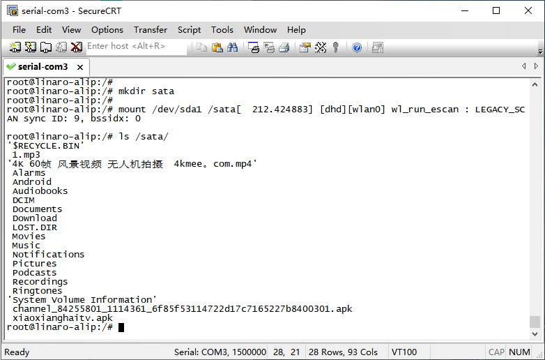
mkdir /mnt/sata //create a Mount Point
mount /dev/sda /mnt/sata/ //mount SATA
ls /mnt/sata/ //view SATA contents
df -h //view the space size of the mounted disk
6.15 M.2 NVME SSD
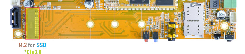
❶ Connect the SSD to the development board and power on.
❷ Format SSD to ext4 format. If the SSD is in ext4 format, skip this step.
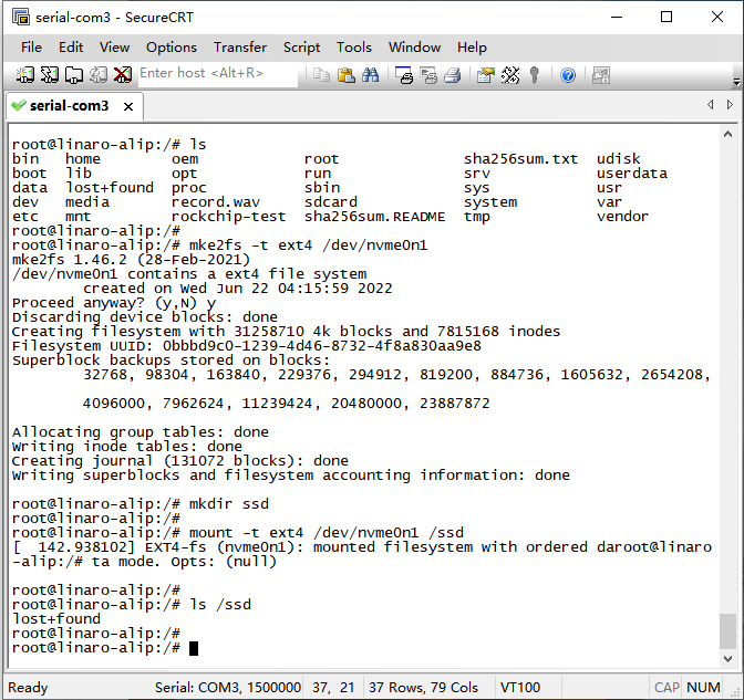
mke2fs -t ext4 /dev/nvme0n1 //format SSD to ext4
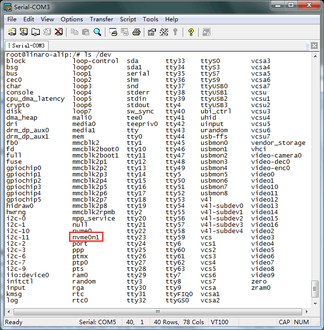
❸ Mount SSD.
ls /dev                            //view device name
mkdir ssd                          //create a Mount Point
mount -t ext4 /dev/nvme0n1 /ssd    //mount SSD to a new directory
ls /ssd                            //view SSD contents
df -h                              //view the space size of the mounted disk
6.16 4G & GPS
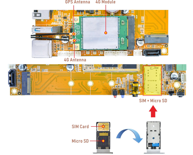
6.16.1 4G
❶ Insert 4G module to PCIe socket (4G model: EC20).
❷ Connect antenna and insert SIM card.
❸ Power on.
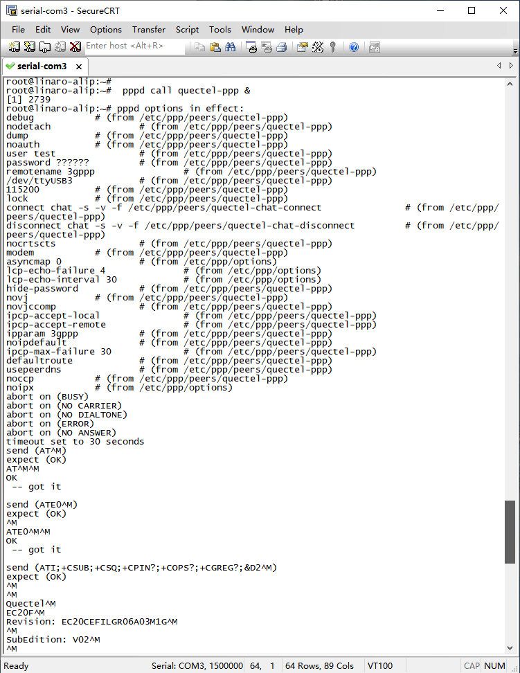
❹ Execute commands to connect 4G network.
mkdir /var/run/pppd
mkdir /var/run/pppd/lock
pppd call quectel-ppp &
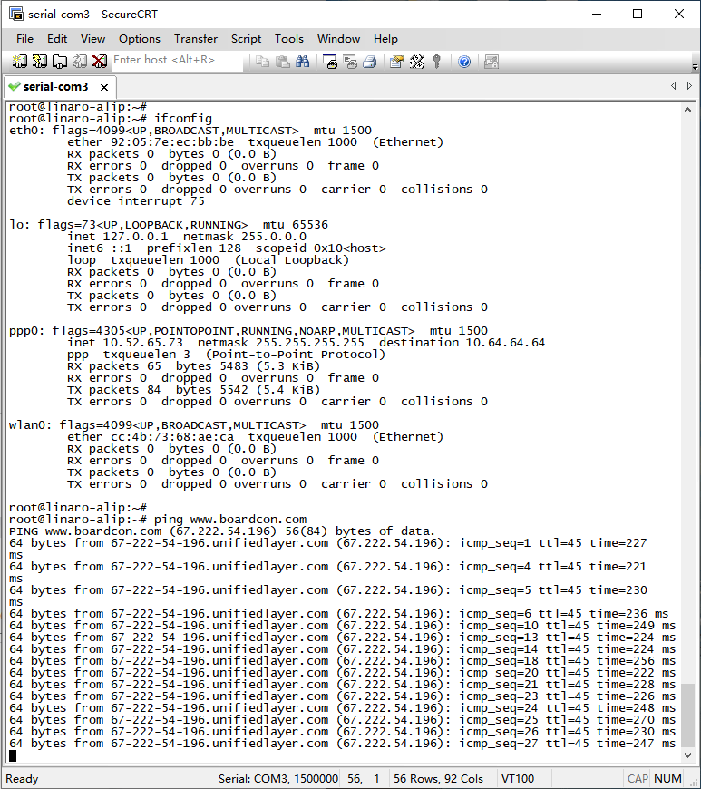
❺ Test network.
ifconfig
ping -I ppp0 www.armdesigner.com

6.16.2 GPS
❶ Plug the EC20 module to PCIe socket.
❷ Connect GPS antenna.
❸ Power on.
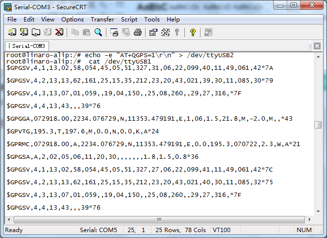
❹ Execute commands to test GPS.
echo -e "AT+QGPS=1\r\n" > /dev/ttyUSB2
cat /dev/ttyUSB1
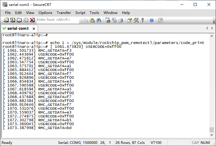
6.17 IR
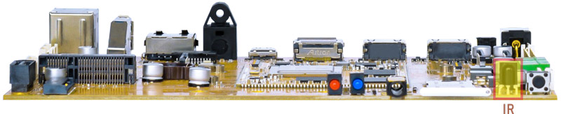
❶ Turn on IR.
echo 1 > /sys/module/rockchip_pwm_remotectl/parameters/code_print
❷ Press the Infrared controller, you can view the received datas on the terminal.
6.18 Keys
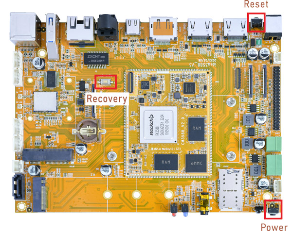
Recovery It is used when flashing the image. Connect the USB Type-C cable, press and hold the Recovery key, power on, it will enter the loader mode.
Power Short press - sleep/wake; Long press - shut down and restart the process.
Reset Restart the board.