6. Debian Application
6.1 Display
Display IO
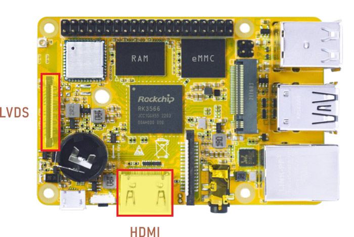
Compact3566 supports HDMI and LVDS display. Connect the board and monitor with a HDMI cable, then power on.
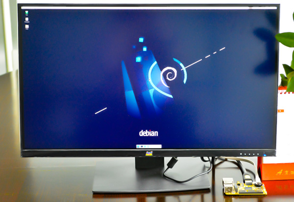
HDMI Display
Note
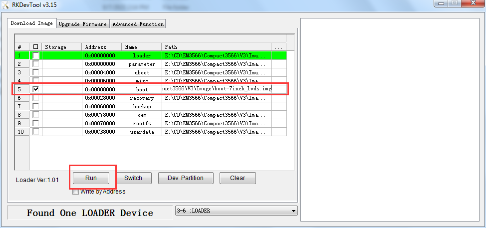
The Boardcon factory default HDMI display. If change to LVDS LCD, please reflash the corresponding boot.img.
10.1” LVDS LCD:
boot_10.1inch_lvds.img7” LVDS LCD:
boot_7inch_lvds.imgHDMI:
boot_hdmi.img
6.2 Audio IO
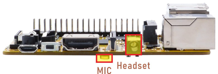
1aplay -l                           //list available sound cards
2arecord -D hw:1,0 -f cd test.wav   //record and store as test.wav. Priority: headset > MIC
3aplay -D plughw:1,0 test.wav       //play test.wav, sound card 1, device 0
6.3 Video Player
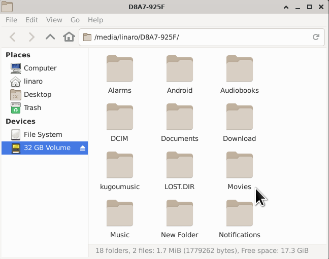
Copy the video file to SD card/U-disk and plug it into the board. After the system starts, open SD card/U-disk and execute the following command to play.
1gst-play-1.0 --flags=3 --videosink=xvimagesink /usr/local/test.mp4 //play `test.mp4`
or
1gst-play-1.0 --videosink=xvimagesink XXX //`XXX` is vedio file path
1export GST_MPP_VIDEODEC_DEFAULT_ARM_AFBC=1           //set AFBC
2cat /sys/kernel/debug/dri/0/state | grep "plane\["   //view the plane id (select Cluster0-win0)
3GST_DEBUG=*mpp*:4 gst-play-1.0 --flags=3 --videosink="kmssink plane-id=70" /XXX   //play video(`XXX` is the video file path)
4GST_DEBUG=*mpp*:4 gst-play-1.0 --flags=3 --videosink="kmssink plane-id=70" /media/linaro/NEW/4K.mp4 --audiosink="alsasink device=hw:1,0"  //specify audio channel output
6.4 Micro SD
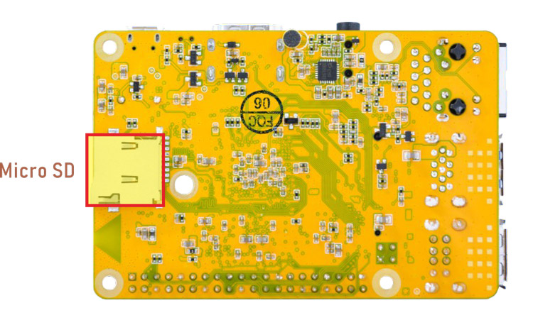
Micro SD
Compact3566 supports SD Hot-plug.
SD
6.5 USB Host
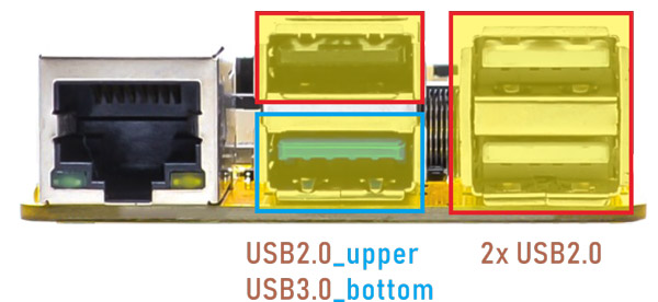
Compact3566 features 1x USB3.0 and 3x USB2.0 Host(USB OTG can be used for Host).
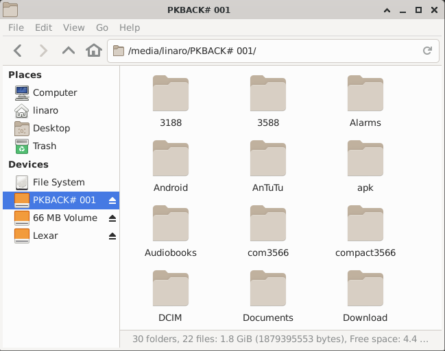
USB device
The USB3.0 default support Superspeed.
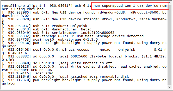
Superspeed
6.6 M.2 SSD
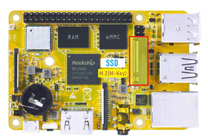
M.2 SSD
Connect the SSD to the development board before power on. Then execute follow command to erase SSD and mount.
1ls /dev            //view SSD device name
2mke2fs -t ext4 /dev/nvme0n1           //if SSD is not ext4 format, format it to ext4
3mkdir /mnt/ssd                        //create a new directory
4mount -t ext4 /dev/nvme0n1 /mnt/ssd   //mount SSD to the new directory
5ls /mnt/ssd                           //view the contents of the ssd
6.7 WiFi & Bluehost
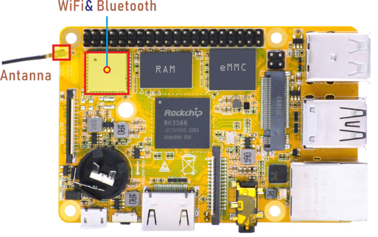
WiFi & Bluehost
6.7.1 WiFi
❶ connect the WiFi antenna.
❷ click the network icon of the UI interface.
❸ select the SSID from the list of available networks and enter the password.
After connected, ping URL/IP at terminal to test.
1ifconfig
2ping www.boardcon.com
6.7.2 Bluetooth
❶ turn on bluetooth.
1bt_load_rtk_firmware
❷ click the Bluetooth icon of the desktop and select the Devices… option.
bluetooth icon
❸ click the Search to start searching and select the available device in the list to pair.
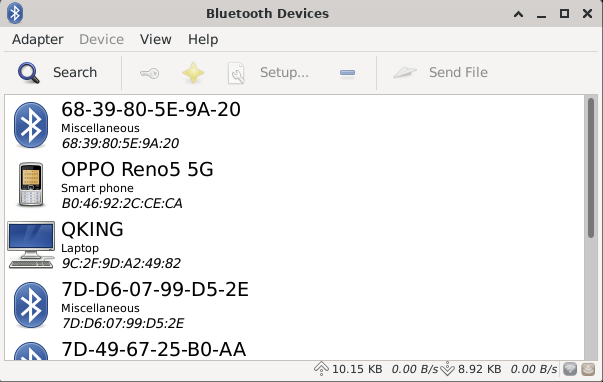
Available device
After pairing, devices can connect with each other automatically.
6.8 Ethernet
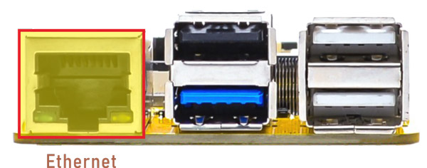
Ethernet
Connect the board and router with an Ethernet cable (default DHCP=Yes). User can ping URL/IP at terminal, or open the browser to test Network.
1ifconfig
2ping www.boardcon.com
6.9 RTC
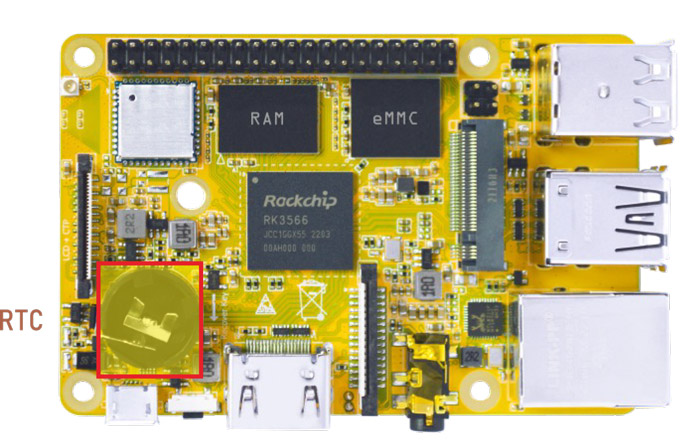
RTC
❶ insert a CR1220 battery before test. It keeps the time running when the main power is off.
❷ execute the follow command to set the RTC time.
1date "2024-11-06 10:15:30"              //set system date
2hwclock -w                              //set the hardware clock to current system time
3hwclock                                 //display date and time
root@linaro-alip:/# date -s "2024-11-06 10:15:30"
Wed Nov  6 10:15:30 UTC 2024
root@linaro-alip:/# hwclock -w
root@linaro-alip:/# hwclock
2024-11-06 10:15:43.492278+00:00
root@linaro-alip:/# hwclock
2024-11-06 10:15:56.176138+00:00
root@linaro-alip:/# hwclock
2024-11-06 10:16:05.824220+00:00
root@linaro-alip:/#
6.10 Expansion
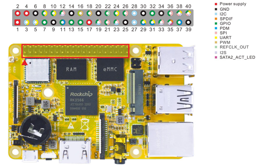
Expansion
6.10.1 UART
The UART loopback test is for reference only.
❶ copy com to SD card and then insert it to the card slot.
❷ power on. After the system boot, execute the command to copy com from SD card to the board.
1copy /media/linaro/New/com /system  //com absolute path: /media/linaro/New/
2chmod 777 /system/com               //modify com file properties
❸ connect the transmit (TX) pin to the receive (RX) pin of UART. After executes the command, input character to test UART.
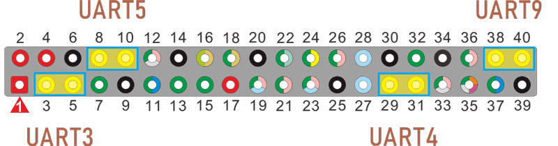
UART
UART3(ttyS3): Pin5(TX), Pin3(RX)
UART4(ttyS4): Pin29(TX), Pin31(RX)
UART5(ttyS5): Pin8(TX), Pin10(RX)
UART9(ttyS9): Pin40(TX), Pin38(RX)
1./system/com /dev/ttyS3 115200 8 0 1 //test UART3
root@linaro-alip:/# ./system/com /dev/ttyS3 115200 8 0 1
port = /dev/ttyS3
baudrate = 115200
cs = 8
parity = 0
stopb = 1
5656565656
RECV: 5656565656
jkjkjkjk
RECV: jkjkjkjk
❹ press Ctrl + C to exit UART3 testing, execute the command to test UART4.
1 ./system/com /dev/ttyS4 115200 8 0 1 //test UART4
root@linaro-alip:/# ./system/com /dev/ttyS4 115200 8 0 1
port = /dev/ttyS4
baudrate = 115200
cs = 8
parity = 0
stopb = 1
12345678
RECV: 12345678
asdfgh1234
RECV: asdfgh1234
The method for testing UART5(ttyS5) and UART9(ttyS9) is similar.
6.10.2 SPI
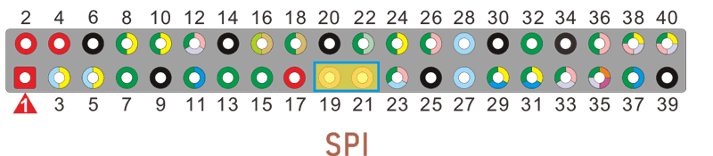
pin19: SPI0_MOSI_M0
pin21: SPI0_MISO_M0
Execute the following command after short-circuit SPI0_MOSI_M0 and SPI0_MISO_M0 of SPI0, you can see the change of SPI0 data.
1spidev0.0_test
 root@linaro-alip:/# spidev0.0_test
 spi mode: 0
 bits per word: 8
 max speed: 500000 Hz (500 KHz)

 FF FF FF FF FF FF
 40 00 00 00 00 95
 FF FF FF FF FF FF
 FF FF FF FF FF FF
 FF FF FF FF FF FF
 DE AD BE EF BA AD
 F0 0D
 root@linaro-alip:/#
6.10.3 IR
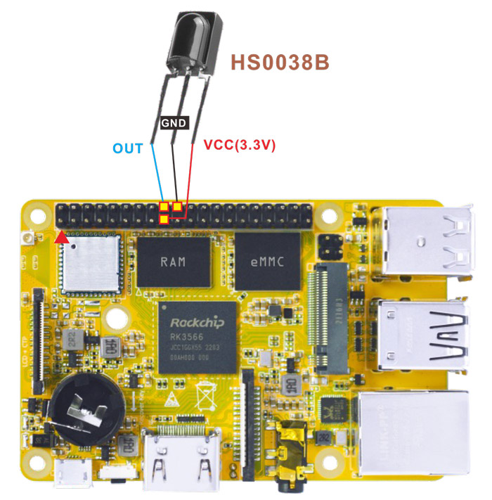
IR connection
❶ connect IR receiver and board.
OUT: connect to PWM3_IR (pin18)
GND: connect to Ground
VCC: connect to 3.3V
❷ execute the command:
1echo 1 > /sys/module/rockchip_pwm_remotectl/parameters/code_print //obtain the data
❸ operate the IR controller and view the received data.
 root@linaro-alip:/# echo 1 > /sys/module/rockchip_pwm_remotectl/parameters/code_print
 [ 126.606807] USERCODE=0xbf40
 [ 126.634707] RMC_GETDATA=b9
 [ 127.333994] USERCODE=0xbf40
 [ 127.361855] RMC_GETDATA=b8
 [ 127.798060] USERCODE=0xbf40
 [ 127.825960] RMC_GETDATA=e2
 [ 128.327603] USERCODE=0xbf40
 [ 128.355568] RMC_GETDATA=e6
6.11 Camera
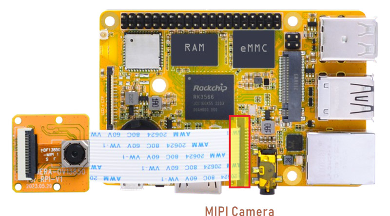
Camera
Connect the camera module (OV13850) to the development board before power on.
1grep ov13850 /sys/class/video4linux/v*/name //check device number
2grep "" /sys/class/video4linux/v*/name | grep mainpath
3gst-launch-1.0 v4l2src device=/dev/video8 ! video/x-raw,format=NV16,width=1280,height=800, framerate=30/1 ! kmssink //preview
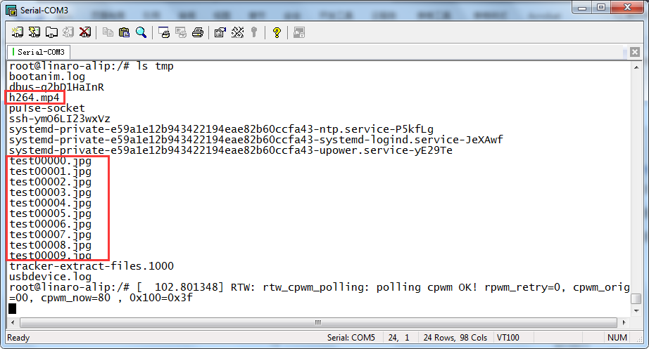
4gst-launch-1.0 v4l2src device=/dev/video8 num-buffers=100 ! video/x-raw,format=NV12,width=1920,height=1088,framerate=30/1 ! videoconvert ! mpph264enc ! h264parse ! mp4mux ! filesink location=/tmp/h264.mp4 //Video recording
5gst-launch-1.0 -v v4l2src device=/dev/video8 num-buffers=10 ! video/x-raw,format=NV12,width=1280,height=800 ! mppjpegenc ! multifilesink location=/tmp/test%05d.jpg //take a picture
Files storage path is /tmp